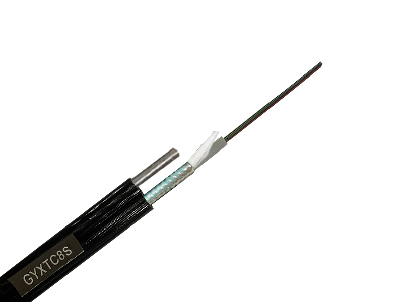
GYXTC8S type optical cable is a central tube filled, steel-polyethylene bonded sheathed, 8-shaped self-supporting outdoor optical cable for communication.
Erection Method:Overhead
Standard:Comply with stand YD/T 1155-2001 as well as IEC60794-1.
Temperature Range:Storage and operation::-40C ~ +70C;Erection:-15C ~ +60C
Bend radius:Static 10 times the cable diameter,Dynamic 20 times optical cable diameter
Application:Core Network, Metropolitan Area Network, and Access Network ,Applicable to long-distance communication and inter-office communication Outdoor Optical Cable
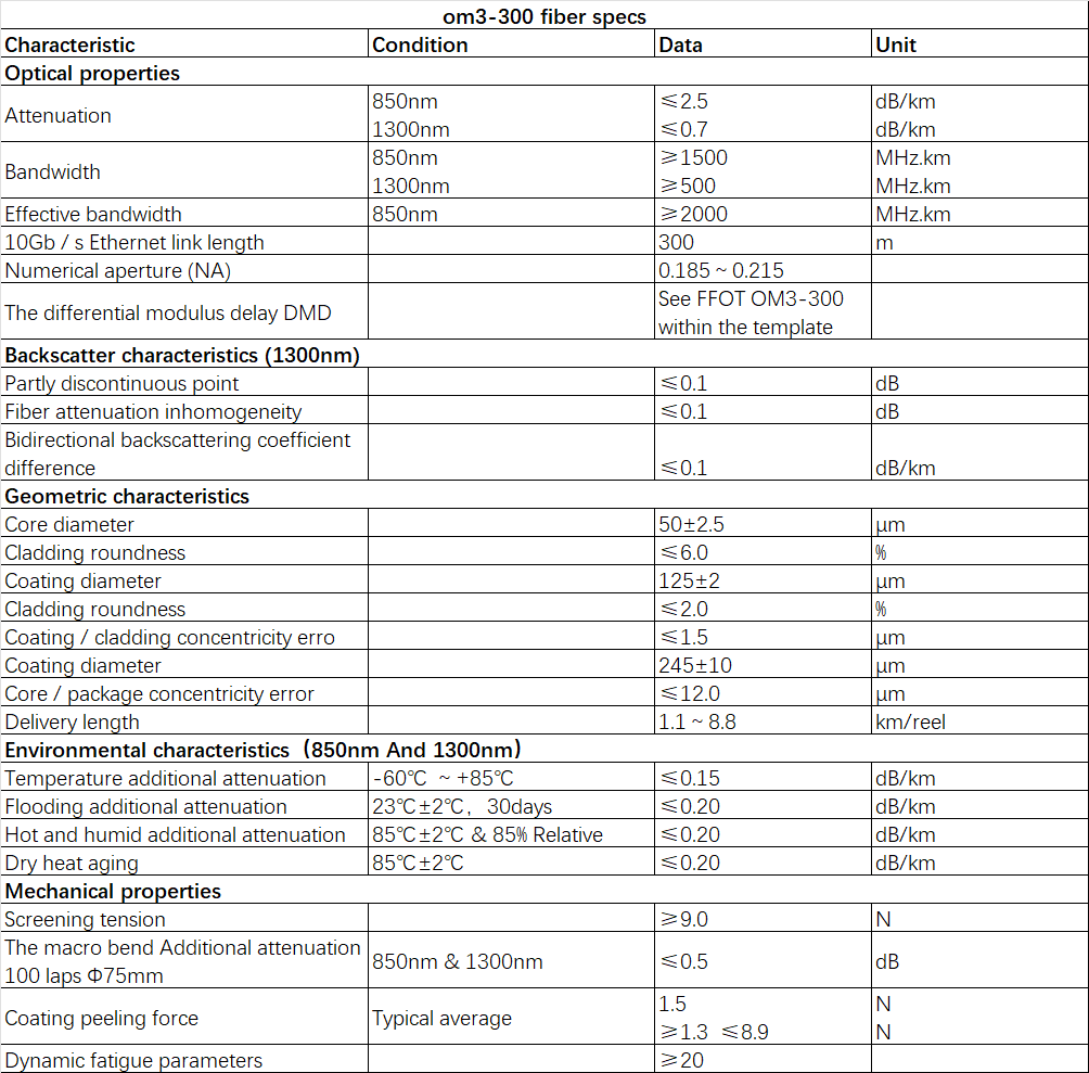
Fiber Type:G652D;G655C;G657A1;G657A2;50/125;62.5/125;OM3-150;OM3-300;OM4 As Options

1、Full-section water-blocking structure to ensure good water-blocking performance
2、The loose tube is filled with special grease to provide critical protection for the optical fiber.
3、The 8-shaped self-supporting structure has high tensile strength, is easy to lay overhead, and has low installation cost.
4、Steel-plastic composite tape armoring increases the tensile strength and lateral pressure resistance of optical cables
5、The polyethylene sheath makes the optical cable have good UV resistance.
6、Product service life is more than 30 years
Optical Fiber Colors:


There are two ways to lay out overhead optical cables: one is the fixed pulley traction method, including manual traction method and mechanical traction method; the other is the optical cable drum moving release method.
1、Fixed pulley traction method
When hanging optical cables, first set up the optical cable drum to be placed, and fix the large pulleys for laying out optical cables on the poles at the upper and lower leads. On the hanging wire in each pole, every 10 to 20m Hang a small pulley (guide pulley) and thread the traction rope into the small pulley. Then, prepare the traction head and connect the traction rope with the optical cable, ready for deployment.
When manual traction is used, the optical cable drum is manually pushed to gradually release the optical cable, and then a person is set up on every other pole to assist in traction (guide pulleys are installed on the angle poles if necessary). Gradually tighten the traction rope at the traction end to slowly let out the optical cable. In order to fully ensure the safety of optical fiber, three contact telephones should be installed at the cable unwinding end, cable retracting end and optical cable pulling head, and communication should be kept open at all times. When a single disk of optical cable is long, it is generally laid out in two steps: after laying out the first half of the disk, turn the “8” on the spot, and then lay out the second half of the disk in the other direction.
When mechanical traction is used, the mechanical traction host should be placed at the cable retracting end, and the auxiliary traction machine should be placed at the appropriate position for erecting the route. Set up the optical cable drum to be placed at the cable unwinding end, and manually push the optical cable drum to gradually release the optical cable from the top of the drum. Machinery is used instead of manual pulling to achieve the purpose of laying the optical cable. When making the traction end, it must be ensured that the traction force mainly acts on the reinforcement of the optical cable. Within the limit of the allowable traction force of the optical cable, the length of the optical cable laid at one time should depend on the terrain conditions. In addition, the pulling speed of the optical cable pulling machine must be determined in advance. When the traction tension exceeds the standard, there must be an automatic cut-off or alarm device.
After the fiber optic cable is laid out, the length of the fiber optic cable required for the joint and the length of the fiber optic cable reserved for each pole should be reserved. Finally, hang the remaining cable with the wrapped ends on the pole.
When laying out suspended overhead optical cables, telescopic bends can be appropriately made on the poles. In the medium load area, heavy load area, and super heavy load area, it is generally required to have a reservation on each pole; in the light load area, every 3 ~5 rods are reserved; for ice-free areas, no reservation is required (but the cable cannot be pulled too tight when laying out, and pay attention to the natural sag). The specifications of the telescopic bend of the optical cable on the pole should be protected by polyethylene bellows at the center of the pole, with a reserved length of 2
m (generally not less than 1.5m). Reserve both sides and binding parts, and be careful not to tie them tightly so that they can expand and contract freely when the temperature changes, thus protecting the optical cables. When the optical cable passes through the “Ten”-shaped hanging wire or the “T”-shaped hanging wire, a protective tube should also be installed.
Hooks are generally used to fix and hang overhead optical cables. The distance between optical cable hooks is 50 cm, and the allowable deviation should not be less than ±3
cm. The buckle direction of the hook on the hanging wire should be consistent, the hook support plate should be complete, and there should be no mechanical damage. The distance between the first hook on both sides of the pole and the hanging wire splint should be 25 cm, and the allowable deviation shall not be greater than ±2 cm.
2、Optical cable drum moving and releasing method
This hanging method is to mount the optical cable drum on the truck (fix one end of the optical cable at the hanging wire of the electric pole), manually push the optical cable drum, and let the optical cable be laid along the overhead pole while hanging the optical cable on the hanging wire. After one pole span is laid out, the optical cable can be fixed on the hanging wire and the next pole span can be laid out. This deployment method is simple to operate, but the use of trucks to erect is subject to conditions. When using this method, the following conditions should generally be met.
①The width of the road can allow vehicles to travel.
②The distance between the overhead pole road and the roadside shall not be greater than 3 m.
③There are no obstacles in the erection section.
④The hanging wire is located at the lowest level of other lines on the pole road.
Standard length:2000m, other lengths are also available
Note: The structure’s size and specifications can be desianed according to customer requirements
