
Submarine optical cables are mainly used for optical signal transmission. To improve the reliability and safety of submarine optical cables, they are optical-electric composite cables. The interior of submarine optical cables is composed of multi-core single-mode optical fiber units and copper conductors. For use in Neritic Zone with a water depth of less than 500m. The mechanical structure design of submarine optical cables should meet the requirements of laying water depth, construction and maintenance.
ISO-9001 Quality management systems – requirements
ISO-14001 Environmental management systems
ISO-45001 Occupational health and safety management systems
ITU-T G.978 Characteristics of optical fibre submarine cable
IEC-60793 Optical fibers
IEC-60794-3 Optical fibre cable-Part3:Outdoor cables – Sectional specification
ITU-T-G.652 Characteristics of a single-mode optical fiber and cable
EIA/TIA-598 Optical fiber cable color coding
ASTM E29- 13 Standard practice for using significant digits in test data to determine conformance with specifications
GJB-4489-2002 General specifications for submarine optical cables
GB/T 18480-2001 Specifications for submarine optical cables
GB/T15972-2008 Specifications for optical fiber test methods
GB/T 51154-2015 Code for engineering design of optical fiber submarine cable systems
Submarine optical cable is the main component of the underwater system, connecting underwater equipment such as splitters and sensors, and performing the function of optical signal transmission.
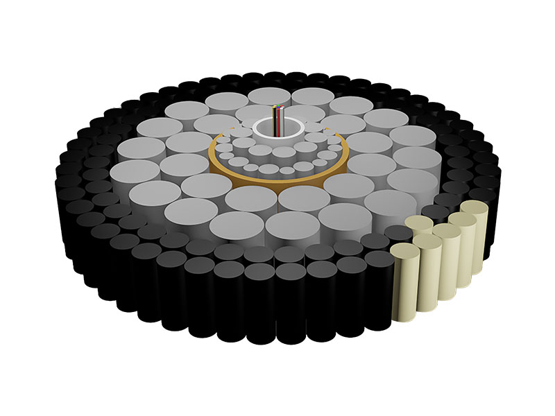
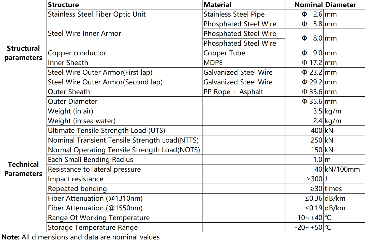
The structure of double-armored submarine cable (DA). The submarine cable consists of optical fiber unit, central stainless steel loose tube, inner armor steel wire, welded copper tube conductor, PE insulation sheath, double-layer steel wire outer armor, anti-corrosion asphalt, polypropylene rope outer layer; the cable core is filled with water-blocking longitudinal sealing material.

3.3.1 Mechanical properties
a) Ultimate Tensile Strength Load (UTS): ≥400kN;
b) Nominal Transient Tensile Strength Load(NTTS): ≥250kN;
c) Normal Operating Tensile Strength Load(NOTS): ≥150kN;
d) Side pressure resistance: ≥40kN/100mm;
e) Impact resistance: ≥300J;
f) Minimum bending radius: ≤1.0m;
g) Number of repeated bending: ≥30 times;
h) When the submarine cable is subjected to mechanical performance test, the additional attenuation of the optical fiber should not be greater than 0.05dB, and the optical fiber should not have permanent additional attenuation after the test (when the absolute value of the measured value is not greater than 0.03dB, it is judged to have no additional attenuation);
i) When the submarine cable is subjected to working tensile load test, the optical fiber should not have elongation (when the absolute value of the measured value is not greater than 0.005%, it is judged to have no elongation);
j) When the submarine cable is subjected to a short tensile load test, the elongation of the optical fiber shall not exceed 0.15%.
3.3.2 Structural performance
a) Weight per unit length: ≤3.5kg/m;
b) Diameter: ≤35.6mm;
c) Single-section manufacturing length: ≥90km (the specific length of a single section is determined by the design).
3.3.3 Optical performance
This project uses G.652D optical fiber, and the test method should meet the test specifications of GB/T15972-2008.
The main technical indicators of G.652D are as follows:
a) Fiber attenuation coefficient in finished submarine cable: ≤0.19dB/km (@1550nm);
b) Screening intensity: ≥1.38GPa;
c) Fiber margin: <5‰;
d) Number of fiber cores: 24 cores.
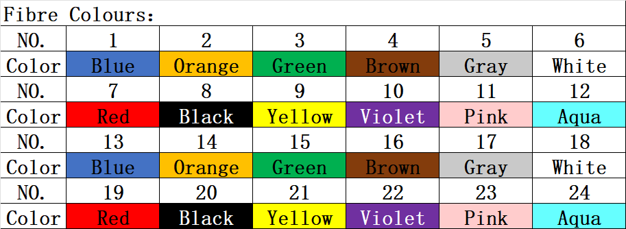
The optical fiber color spectrum is shown in Table

Note: The color of optical fiber after No. 12 is added to the basic color
3.3.4 Electrical performance
a) Insulation resistance of conductor and stainless steel loose tube to ground: ≥10GΩ•km (20℃);
b) DC resistance of conductor: ≤1.0Ω/km (20℃);
c) DC voltage of conductor and stainless steel loose tube to ground: 5kVDC, no breakdown for 3 minutes.
3.3.5 Appearance and identification
a) The submarine cable should be marked with end A and end B, with end A being the top and end B being the bottom. The name of each section of the submarine cable should be marked, and a length sign should be set at intervals of 500m for each section of the submarine cable;
b) The sign has black characters on a white background, and the characters are clear and will not be blurred due to moisture. The sign should be firmly tied and should not fall off during transportation and laying;
c) The length number of the submarine cable on the sign should be large enough to be easy for operators to read when the submarine cable is moving;
d) During the life of the submarine cable, the mark should be clear and durable, not corroded, and the length accuracy of the mark should be higher than ±1m/1000m.
3.3.6 Working life
Not less than 25 years.
3.3.7 Environmental adaptability
a) Working temperature range is -10℃~40℃;
b) Storage and transportation temperature range is -20℃~50℃;
c) Longitudinal watertightness: ≤200m (one-way water seepage length, 5MPa water pressure, 14d).
The warranty period shall be based on the warranty period specified by the end user and shall not be less than five years, starting from the date of acceptance by the end user.
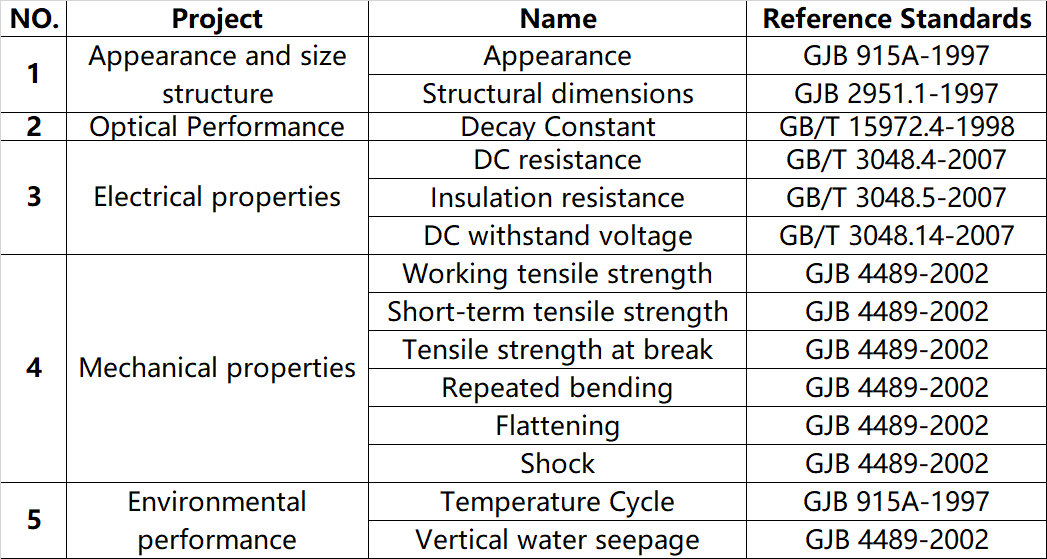
The acceptance of submarine optical cables mainly refers to the relevant requirements of GBT 18480-2001 and GJB4489-2002.
Submarine cable acceptance criteria
