FTTH co-construction and sharing solution for new residential areas
1、Project background
In recent years, FTTH fiber-to-the-home residential broadband services have developed rapidly. In order to achieve equal access, the three major operators have built their own projects, resulting in problems such as high investment costs and duplication of construction. In order to avoid duplication of construction, a new residential FTTH access network construction plan is proposed, namely the FTTH co-construction and sharing plan.
According to the spirit of the documents of the Ministry of Industry and Information Technology, “co-construction and sharing” between telecommunications infrastructure will become the direction of future development. Residential broadband with a large amount of construction should realize co-construction and sharing, so that not only can the broadband be co-constructed and shared with limited investment, It achieves optimal resource allocation, enriches consumers’ choices, and also brings convenience to the management of weak current cables in the community.
2、Design basis
National norms and standards:
《Integrated Wiring System Engineering Design Specifications》(GB 50311-2016)
《Integrated wiring system engineering acceptance specifications》(GB 50312-2016)
《Technical specifications for lightning protection of building electronic information systems》(GB 50343-2012)
《Specifications for construction and acceptance of electronic information system computer rooms》GB_50462-2008
《Computer room design specifications》(GB50174-2008)
《Code for acceptance of construction quality of electrical engineering projects》( GB50303-2002)
《Engineering design specifications for fiber-to-the-home communications facilities in residential areas and residential buildings》( GB50846-2012)
3、Scheme design
1)Plan overview
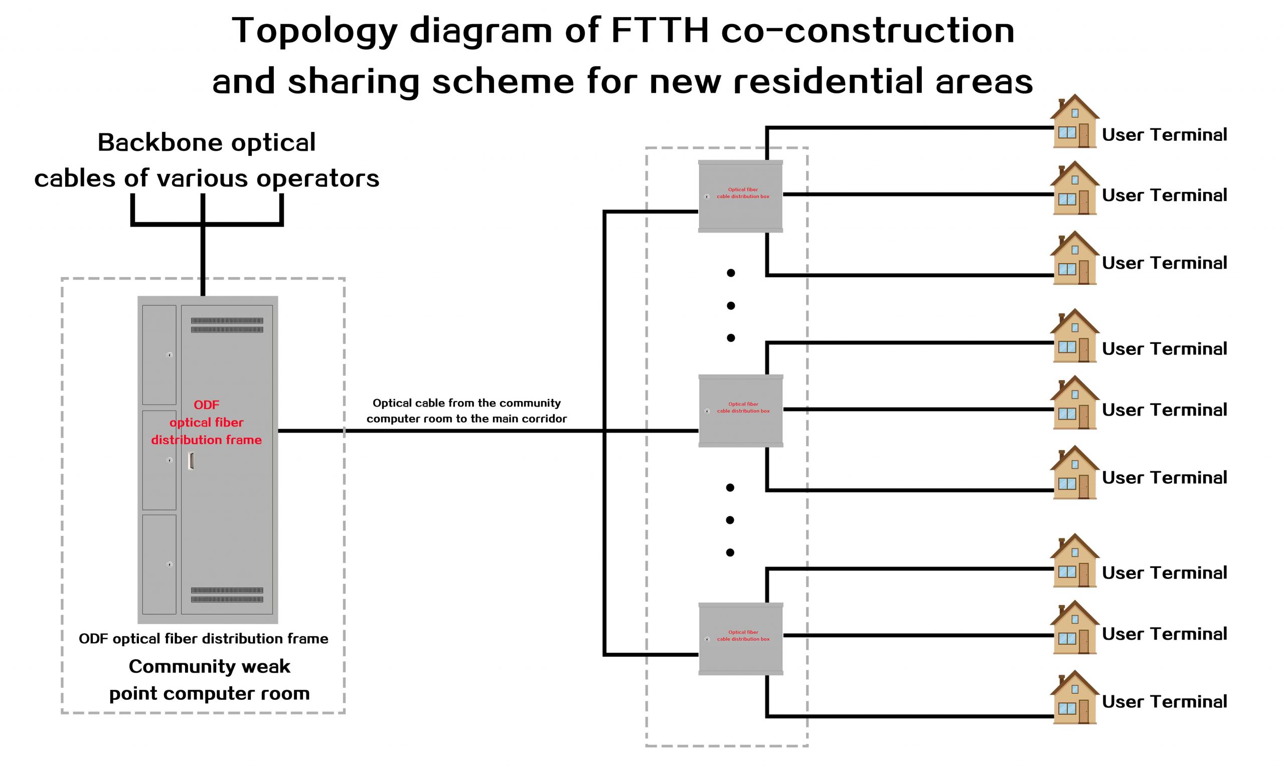
This solution is aimed at newly built residential communities. The FTTH optical splitting adopts the centralized light splitting mode at the first level of the community’s computer room. A co-constructed and shared ODF optical fiber distribution frame is set up in the community’s weak power room. The operator’s backbone optical cable comes in and is connected to the co-constructed and shared ODF optical fiber distribution frame. Then perform first-level optical splitting, and the optical splitter outlet is directly connected to the corresponding user optical fiber port on the ODF optical fiber distribution frame.
Lay out the distribution optical cable from the computer room of the community to the weak current well of the unit building of the community. Set up the optical cable distribution box with the corresponding number of cores according to the number of users in the weak current well. The optical fiber distribution box uses movable connectors. The incoming distribution optical cable and the household sheath The optical fiber cables are all fused with pigtails, and then coupled and connected through the optical fiber adapter in the optical fiber distribution box. After the leather optical cable is installed in the home, the pigtails are fused in the user’s multimedia information box, and then connected to the ONU.
In the entire system, the optical fiber of each user’s home is directly connected to the ODF optical fiber distribution frame in the weak power room of the community. The operator’s installation and maintenance personnel only need to jump the optical fiber from the ODF optical fiber distribution frame in the weak power room of the community to the corresponding user’s home. Complete the opening of the optical path.
2)Solution topology diagram
3、Product configuration introduction
(1) Jointly build and share ODF optical fiber distribution frame
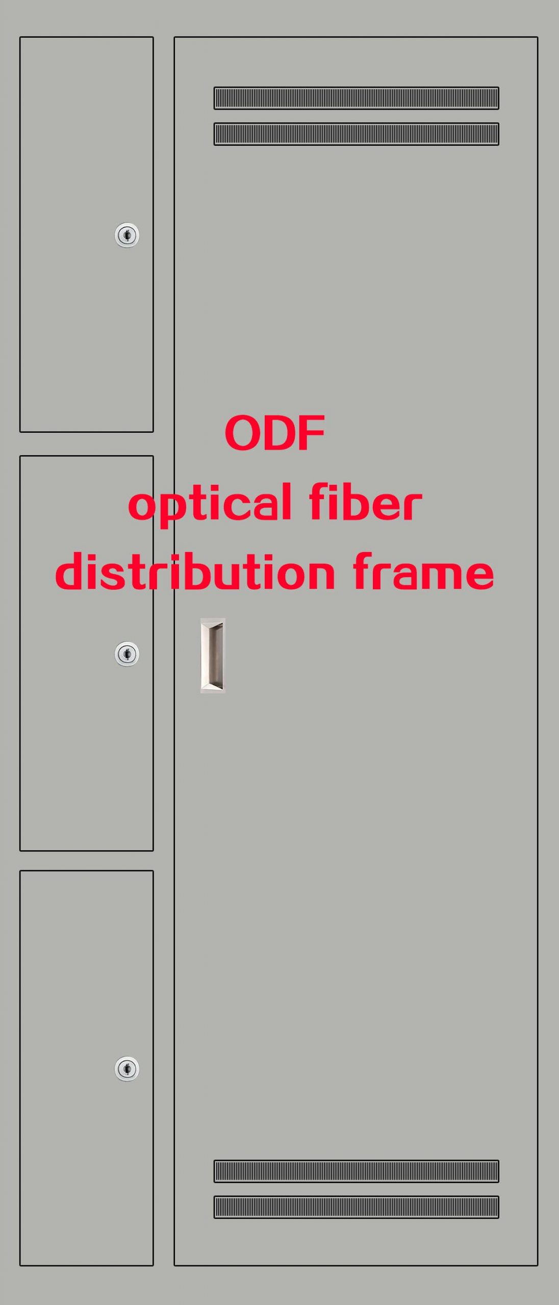
This distribution frame is generally placed in the central computer room of the community and is used to terminate optical cables. Its characteristics are as follows:
1)Maximum number of cores: 720 cores
2)Material: cold rolled plate
3)Plate thickness: 1.2mm (can be customized according to customer requirements)
4)Color: Gray (can be customized according to customer requirements)
5)Number of integrated fiber splicing discs: 60 (can be increased or decreased according to customer requirements)
6)Integrated fiber splicing tray interface: SC/FC/LC optional
7)Size: 2000*800*300mm
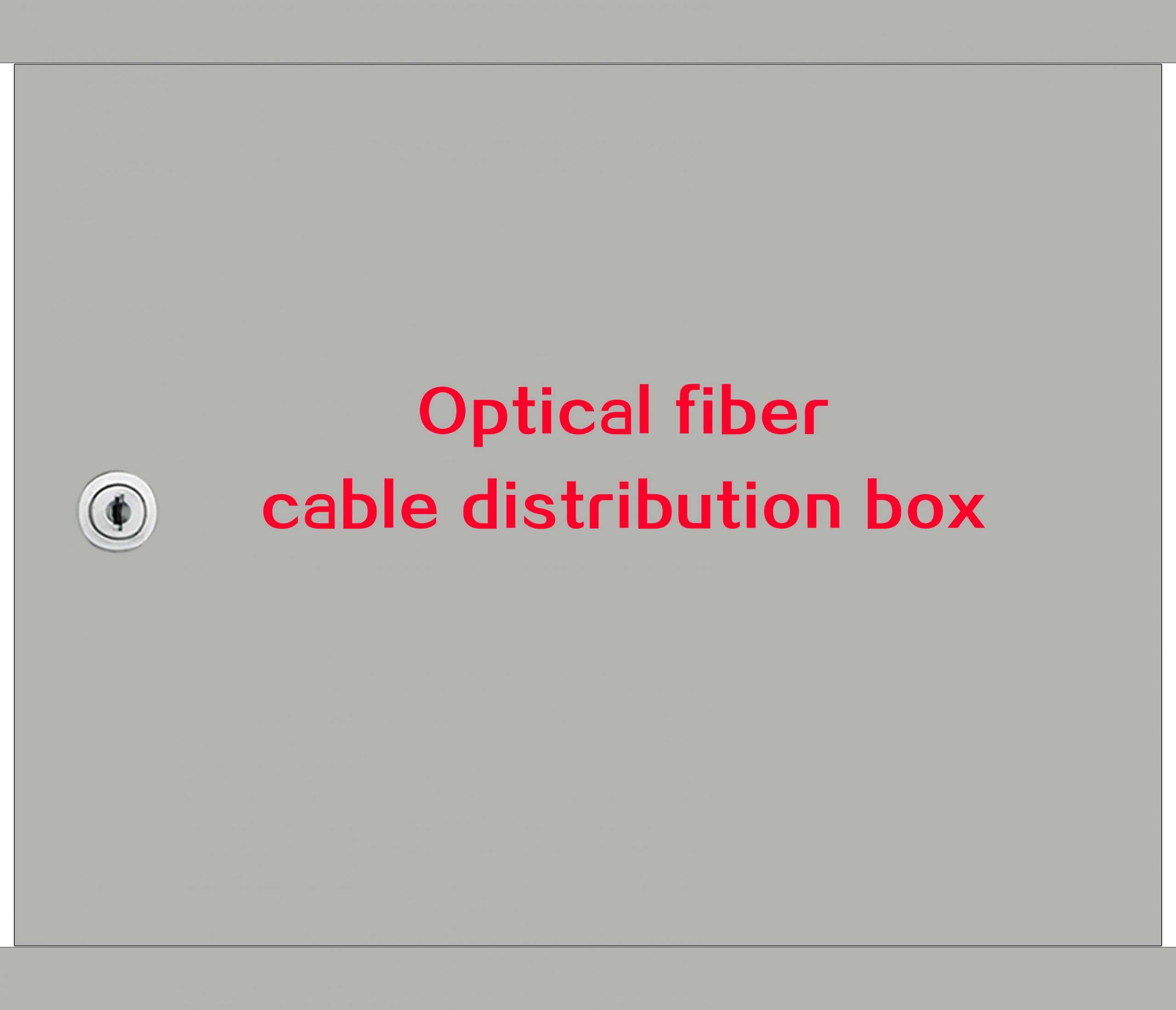
(2) Jointly build and share optical cable distribution boxes
This optical cable distribution box is placed in the weak current well of the corridor, and the number and quantity of cores in the box are selected according to the number of users. Its characteristics are as follows:
1)Number of cores: 24/48/72 cores optional
2)Material: cold rolled plate
3)Plate thickness: 1.0mm (can be customized according to customer requirements)
4)Color: Gray (can be customized according to customer requirements)
5)Adapter panel type: SC/FC/LC optional
6)Size: 440*380*120mm (can be customized according to customer requirements)
(3) Distribution optical cable
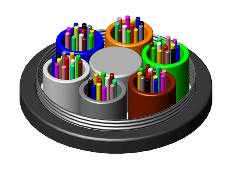
It is used to connect the jointly built and shared distribution frame and the jointly built and shared optical fiber distribution box. The number of cores is selected according to the specific number of users. The structure recommends GYTA. Its characteristics are as follows:
1)Number of cores: 4/6/12/24/36/48/72/96/144 cores optional
2)Structure: GYTA
3)Fiber type: G652D single-mode fiber
4)Outer sheath material: PE
5)Optical cable strengthening core: steel wire
6)Attenuation after cable formation: 1310nm ≤0.36 dB/km; 1550nm ≤0.22 dB/km
(4) Household leather optical cable
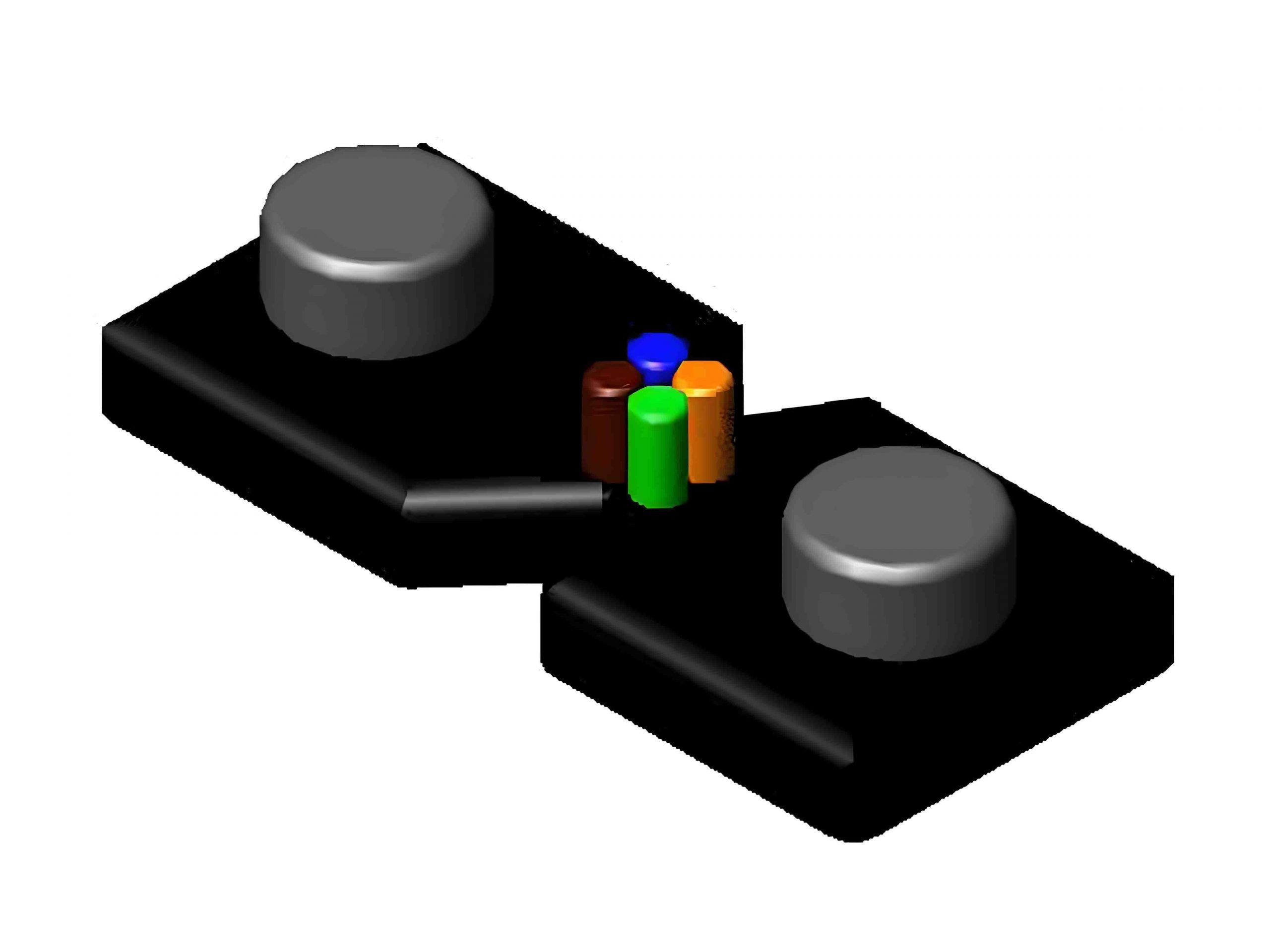
It is used to connect weak current wells in corridors to jointly build shared optical fiber distribution boxes and user-side multimedia information boxes. Its characteristics are as follows:
1)Number of cores: 1/2/4 optional
2)Fiber type: G657A single-mode fiber
3)Optical cable diameter: 2.0×5.0±0.2mm
4)Outer quilt material: LSZH
5)Outer quilt color: black and white optional
6)Attenuation after cable formation: 1310nm ≤0.4 dB/km; 1550nm ≤0.3 dB/km
(5) Optical fiber connectors and pigtails
